
1. How does it work?
1.1 Summary
Many industrial devices operate at 12V or 24V, which exceeds the output capacity of typical microcontrollers like Arduino, as they are limited to 3.3V or 5V and lack sufficient power to drive such loads. The MODSPI Digital Outputs Module addresses this issue by using optocouplers to provide electrical isolation and step up the output voltage to match the supply (VIN), which can range from 12V to 32V.
The module features eight digital outputs, controlled via an SPI IO Expander, allowing you to manage more devices than your microcontroller could handle on its own. Each output is isolated to protect the microcontroller from voltage spikes and other potential hazards, ensuring safe and reliable operation. Additionally, every output includes an indicator LED, offering real-time visual feedback for convenient status monitoring. This module is the ideal solution for integrating industrial devices into your projects with ease and confidence.
1.2 IO Expander
This module leverages the MCP23S17 IO Expander to significantly enhance the digital IO capabilities available to a microcontroller. This module uses the A bus channel configured all for digital outputs. These outputs can be manipulated either individually or in unison, offering flexible integration options for a variety of applications.

1.3 Optocoupler Relay
Each digital output channel on this module is optically isolated with an optocoupler, ensuring that the digital output from the IO expander is safely and efficiently stepped up to match the VDD supply voltage.
Additionally, each channel is equipped with a pull-down resistor to ensure a defined low state when the output is not driven. An indicator LED is also integrated into each channel, providing immediate visual feedback on its operational status.
Note: Due to the small form of the board, the indicator LED is on the output side. The LED won't be on unless VDD is supplied.

2. Specification
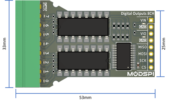
2.1. Form
-
9 way 3.5mm plugable terminal connectors (plug included).
-
Standard MODSPI interface with 8 way, 2.54mm pitch header pins for Power + Comms.
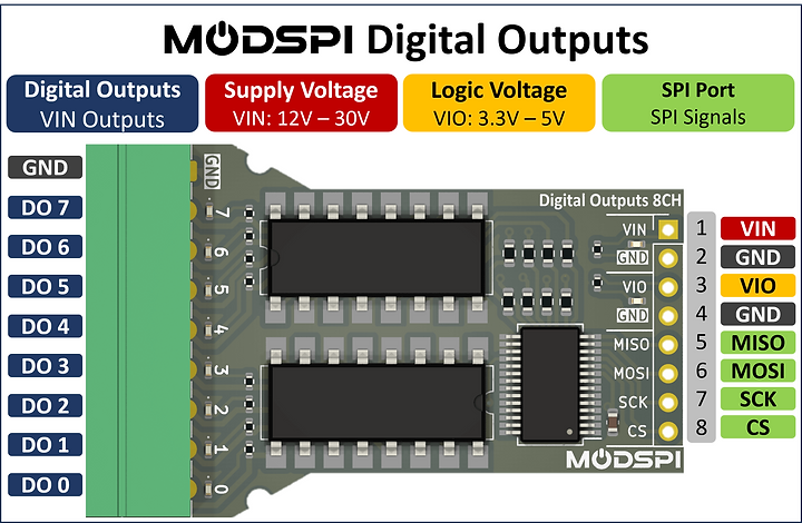
2.2. Pinout
2.3. Electrical Characteristics
Coming Soon...

3. Code
Overview
This example demonstrates how to use the MODSPI_DigitalOutputs class to control a set of digital output channels. The code initializes a MODSPI_DigitalOutputs instance, sets all outputs high and low initially, and then sequentially toggles each output channel in the main loop.
Prerequisites
Ensure you have the MODSPI library installed in your Arduino IDE. If not, you can download and install it from the Library Manager or GITHUB.
Available Functions
Void begin (int chipSelect)
Starts the Initializes the digital output module with the specified chip select pin. If you're using a MODSPI controller you can also put in "BAY1" and select your desired bay.
Void write (int channel, bool state)
Sets the specified output channel (from 0-7) to the given state (HIGH or LOW).
Void writeAll (int8_t state)
Sets all output channels to the specified value, where each bit in the value corresponds to an output channel.
Example Code Breakdown
Include the MODSPI Library
First, we need to include the MODSPI library to access the necessary functions and classes.
#include <MODSPI.h>
Create an Instance of MODSPI_DigitalOutputs
Next you create an instance of the MODSPI_DigitalOutputs class and name it whatever you want, for example outputs1. If you have multiple digital output modules, you will need to create additional instances.
MODSPI_DigitalOutputs outputs1;
Setup Function
The setup function is called once when the Arduino starts. Here, we initialize the instance and perform some initial actions.
void setup() {
// Initialize the outputs1 instance with D5 as the chip select pin.
outputs1.begin(D5); // D5 is the chip select pin.
// Set all of the output channels to LOW.
outputs1.writeAll(0);
}
Main Loop
In the main loop function we cycle through digital outputs 0 to 7, turning each on and off in sequence.
void loop() {
// Loop through digital outputs 0 to 7, turning each on and off in sequence.
for (int a = 0; a <= 7; a++) {
outputs1.write(a, HIGH); // Set the output 'a' to HIGH.
delay(100); // Wait for 100 milliseconds.
outputs1.write(a, LOW); // Set the output 'a' to LOW.
}
}